
-
Products
- Video LCD Module
- Touch Panel
- TFT LCD Panel
- TFT LCD Panel
- T5L Evaluation Board
- Switching Power Supply
- LVDS LCD Module
- Linux LCD Module
- IoT Application
- HMI LCD Module
- HDMI LCD Module
- COF UART LCD Module
-
COB UART LCD Module
- 9.7 Inch
- 8.8 Inch
- 8 Inch
- 7.8 Inch
- 7.4 Inch
- 7 Inch
- 6.8 Inch
- 5.7 Inch
- 5.6 Inch
- 5 Inch
- 4.3 Inch
- 4.1 Inch
- 4 Inch
- 32 Inch
- 3.7 Inch
- 3.5 Inch
- 3 Inch
- 27 Inch
- 23.8 Inch
- 21.5 Inch
- 2.8 Inch
- 2.4 Inch
- 2.1 Inch
- 2 Inch
- 18.5 Inch
- 17.3 Inch
- 15.6 Inch
- 15 Inch
- 14 Inch
- 13.3 Inch
- 12.1 Inch
- 11.6 Inch
- 10.4 Inch
- 10.1 Inch
- 1.6 Inch
- 1.54 inch
- 1.3 Inch
- Android LCD Module
- Catalogue
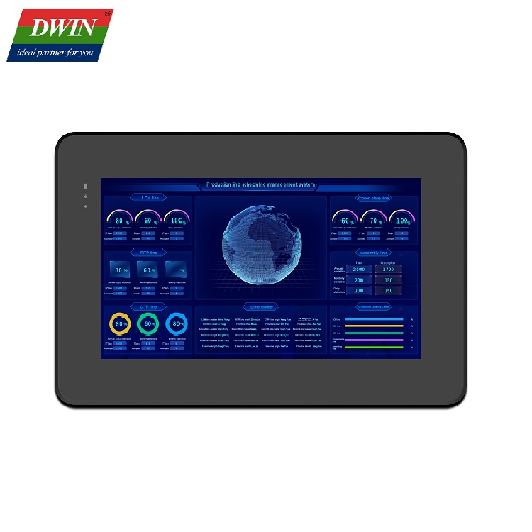


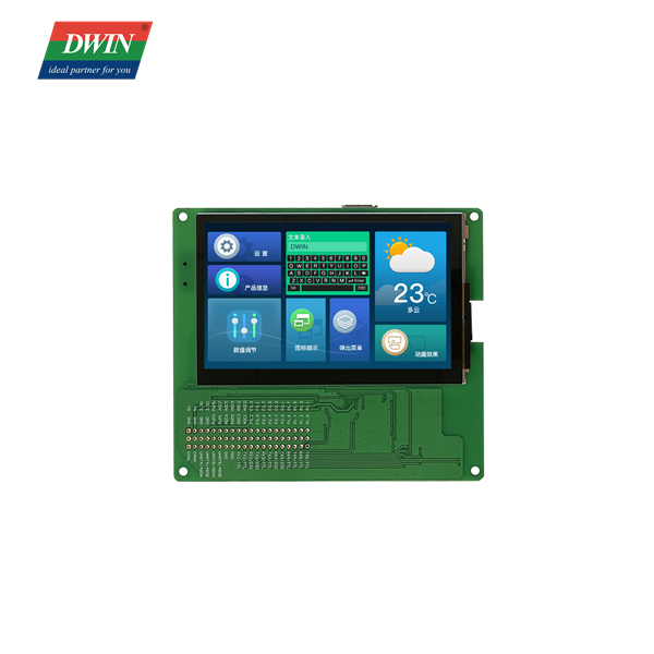
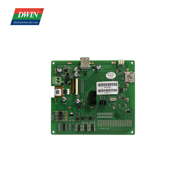
DWIN T5L Drive IC 4.3 Inch Function Evaluation Board <br/>EKT043B
Specification ASIC Information T5L0 ASIC Designed by DWIN. Mass production in 2019, A 600Mhz dua core chip, GUI core and OS core, 1MBytes Nor Flash on the chip, 512KBytes used to store the user database. Rewrite cycle: over 100,000 times Display Color 262K colors Display Area(A.A) 93.60mm (W)×56.16mm (H) Resolution 480 x 800 Backlight LED Brightness 250nit Voltage & Current Power Voltage USB interface : 4.5~5.5V, typical value of 5V 2Pin_3.81 Socket : 6~36V, typical value of 12V Operation Current VCC = 12V, Backlight on, 180mA VCC = 12V, Backlight off, 110mA Reliability Test Working Temperature -20℃~70℃ (12V @ 60% RH) Storage Temperature -30~80℃ Working Humidity 10%~90%RH Protective Paint None Interface Baudrate 3150~3225600bps Output Voltage Output 1, Iout = -4mA;3.0~3.3 V Output 0, Iout =4mA;0~0.3 V Input Voltage Input 1;2.4~5.0V Input 0;0~0.5V Interface UART1: TTL/CMOS Cable Dual-male-USB:HDLUSB1 connect to computer UI & Peripheral UI Version TA / DGUSⅡ ( DGUSⅡ pre-installed ) Peripheral Capacitance touch screen, speaker,WIFI,HME05 simulator Dimension Dimension 126.11(W) × 109.60(H) ×17.70(T) mm Net Weight 145g External Interface PIN Definition Description 1# P1.0 I/O 2# P1.1 I/O 3# P1.2 I/O 4# P1.3 I/O 5# P1.4 I/O 6# P1.5 I/O 7# P1.6 I/O 8# P1.7 I/O 9# P2.0 I/O 10# P2.1 I/O 11# P2.2 I/O 12# P2.3 I/O 13# P2.4 I/O 14# P2.5 I/O 15# P2.6 I/O 16# P2.7 I/O 17# P3.0 I/O 18# P3.1 I/O 19# P3.2 I/O 20# P3.3 I/O 21# ADC1 AD 22# ADC0 AD 23# ADC3 AD 24# ADC2 AD 25# PWM2 PWM 26# ADC4 AD 27# ADC6 AD 28# ADC5 AD 29# PWM1 PWM 30# ADC7 AD 31# PWM3 PWM 32# PWM0 PWM 33# RX3/232 232 34# TX3/232 232 35# RX3/TTL TTL 36# TX3/TTL TTL 37# TX2/232 232 38# RX2/232 232 39# TX2/TTL TTL 40# RX2/TTL TTL 41# GND GND 42# GND GND 43# UART5/485B 485 44# UART5/485A 485 45# UART4/485B 485 46# UART4/485A 485 47# CANH CAN 48# CANL CAN Application