
Specification
| T5L0-Q88 ASIC | T5L0-Q88 ASIC is a small package, low-power, cost-effective, GUI and application highly integratedsingle-chipdual-core ASIC designed by DWIN Technology for small-size LCD and mass produced in 2023. | ||
| Color | 262K colors | ||
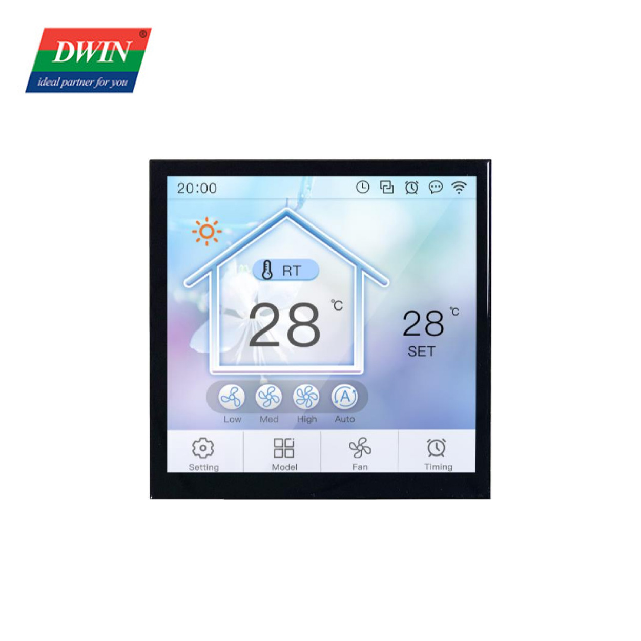
| LCD Type | IPS, TFT LCD | ||
| Viewing Angle | Wide viewing angel, typical value of 85°/85°/85°/85°(L/R/U/D) | ||
| Display Area(A.A) | 71.86mm (W)×70.18mm (H) | ||
| Resolution | 480×480 | ||
| Backlight | LED | ||
| Brightness | DMG48480F040_02WTCZ02:50nit | ||
| Power Voltage | 4.5~5.5V | ||
| Operation Current | 280mA VCC=5V, max backlight | ||
| 100mA VCC=5V, backlight off | |||
| Working Temperature | -10℃~60℃ | ||
| Storage Temperature | -20℃~70℃ | ||
| Working Humidity | 10%~90%RH, typical value of 60% RH | ||
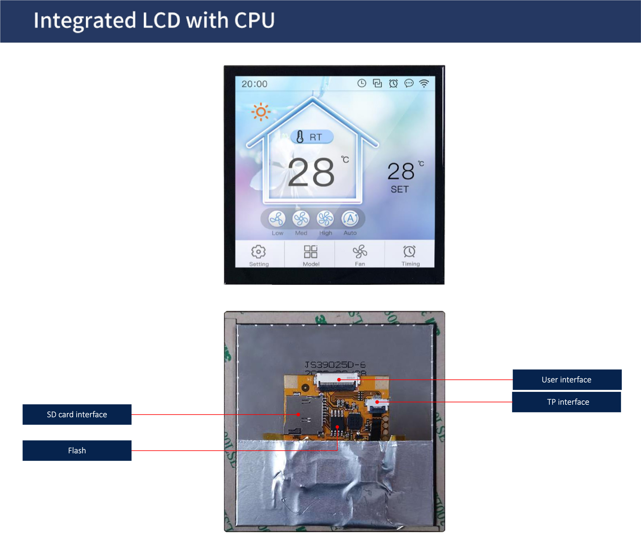
| User Interface | 24Pin_0.5mm FPC | ||
| Baud Rate | 3150~3225600bps | ||
| Output Voltage | Output 1;3.0~3.3 V | ||
| Output 0;0~0.3 V | |||
| Input Voltage |
Input 1;3.3V | ||
| Input 0;0~0.5V | |||
| Interface | UART2: TTL; UART3: TTL;(Only available after OS configuration UART4: TTL;(Only available after OS configuration) |
||
| Data Format | UART2: N81; UART3: N81/E81/O81/N82;4 modes (OS configuration) UART4: N81/E81/O81/N82;4 modes (OS configuration) |
||
|
PIN |
Definition |
Type |
Functional Description |
|
1 |
CAN_TX |
O |
CAN interface |
|
2 |
CAN_RX |
I |
|
|
3 |
TX3 |
O |
UART3 Output |
|
4 |
RX3 |
I |
UART3 Input |
|
5 |
TX2 |
O |
UART2 Output |
|
6 |
RX2 |
I |
UART2 Input |
|
7 |
TR4 |
- |
- |
|
8 |
TX4 |
O |
UART4 Output |
|
9 |
RX4 |
I |
UART4 Input |
|
10 |
TX1 |
O |
UART1 Output |
|
11 |
RX1 |
I |
UART1 Input |
|
12 |
ADC0 |
I |
ADC input. 12-bit resolution in case of 3.3V power supply. 0-3.3V input voltage. |
|
13 |
ADC1 |
I |
|
|
14 |
ADC6 |
I |
Connect the NTC inside the enclosure |
|
15 |
ADC7 |
I |
Connect the NTC located on the enclosure wall |
|
16 |
PWM3 |
O |
Buzzer/speaker driver. The external 10K resistor should be pulled down to the ground to ensure that power-on is low level. |
|
17 |
GND |
P |
GND |
|
18 |
GND |
P |
|
|
19 |
+5V |
P |
Power supply, DC4.5-5.5V. |
|
20 |
+5V |
P |
|
|
21 |
I²C_SDA |
IO |
RTC/proximity sensor/humidity sensor multiplexing. |
|
22 |
I²C_SCL |
IO |
|
|
23 |
EX1 |
IO |
External interrupt (INT1) |
|
24 |
EX0 |
IO |
External interrupt (INT0) |