
-
Products
- Video LCD Module
- Touch Panel
- TFT LCD Panel
- TFT LCD Panel
- T5L Evaluation Board
- Switching Power Supply
- LVDS LCD Module
- Linux LCD Module
- IoT Application
- HMI LCD Module
- HDMI LCD Module
- COF UART LCD Module
-
COB UART LCD Module
- 9.7 Inch
- 8.8 Inch
- 8 Inch
- 7.8 Inch
- 7.4 Inch
- 7 Inch
- 6.8 Inch
- 5.7 Inch
- 5.6 Inch
- 5 Inch
- 4.3 Inch
- 4.1 Inch
- 4 Inch
- 32 Inch
- 3.7 Inch
- 3.5 Inch
- 3 Inch
- 27 Inch
- 23.8 Inch
- 21.5 Inch
- 2.8 Inch
- 2.4 Inch
- 2.1 Inch
- 2 Inch
- 18.5 Inch
- 17.3 Inch
- 15.6 Inch
- 15 Inch
- 14 Inch
- 13.3 Inch
- 12.1 Inch
- 11.6 Inch
- 10.4 Inch
- 10.1 Inch
- 1.6 Inch
- 1.54 inch
- 1.3 Inch
- Android LCD Module
- Catalogue

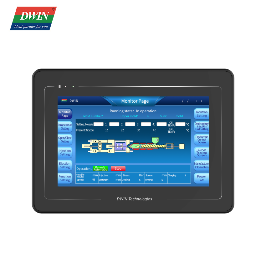

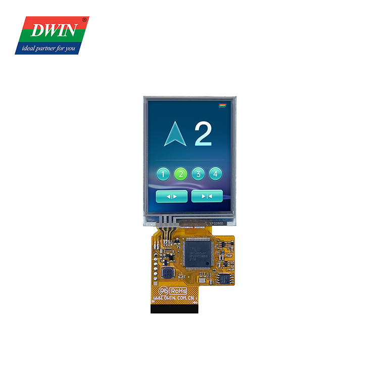

2.8 Inch COF Touch screen Model:DMG32240F028_01W (COF Series)
Video Specification ASIC Information T5L0 ASIC T5L0 ASIC is a low-power, cost-effective, GUI and application highly integrated single-chip dual-core ASIC designed by DWIN Technology for small-size LCD and mass produced in 2020. Display Color 262K colors LCD Type TN, TFT LCD Viewing Angle Normal viewing angle, typical value of 70°/70°/50°/70°(L/R/U/D) Display Area(A.A) 43.2mm(W) ×57.6mm(H) Resolution 240*320 Backlight LED Brightness DMG32240F028_01WN: 350nit DMG32240F028_01WTR: 300nit Touch Parameters Type RTP(Resistive Touch Panel) Structure ITO film + ITO glass Touch Mode Support point touch and drag Surface Hardness 3H Light Transmittance Over 80% Life Dotting > 1,000,000 times; Stroke > 100,000 times; 150g force, back and forth counted as twice Voltage & Current Power Voltage 3.6~5.5V, typical value of 5V Operation Current 110mA VCC=5V, max backlight WTC:- WN:75mA VCC=5V, backlight off Reliability Test Working Temperature -10℃~60℃ Storage Temperature -20℃~70℃ Working Humidity 10%~90%RH, typical value of 60% RH Interface User interface 50Pin_0.5mm FPC Baudrate 3150~3225600bps Output Voltage Output 1;3.0~3.3 V Output 0;0~0.3 V Input Voltage (RXD) Input 1;3.3V Input 0;0~0.5V Interface UART2: TTL; UART4: TTL;(Only available after OS configuration UART5: TTL;(Only available after OS configuration) Data Format UART2: N81; UART4: N81/E81/O81/N82;4 modes (OS configuration) UART5: N81/E81/O81/N82;4 modes (OS configuration) External Interface Pin Definition I/O Functional Description 1 5V I Power supply, DC3.6-5.5V 2 5V I 3 GND GND GND 4 GND GND 5 GND GND 6 AD7 I 5 input ADCs. 12-bit resolution in case of 3.3V power supply. 0-3.3V input voltage. Except for AD6, the rest data is sent to OS core via UART3 in real time with 16KHz sampling rate. AD1 and AD5 can be used in parallel, and AD3 and AD7 can be used in parallel, which equals to two 32KHz sampling AD. AD1, AD3, AD5, AD7 can be used in parallel, which equals to a 64KHz sampling AD; the data is summed 1024 times and then divided by 64 to obtain a 64Hz 16bit AD value by oversampling. 7 AD6 I 8 AD5 I 9 AD3 I 10 AD2 I 11 3.3 O 3.3V output, maximum load of 150mA. 12 SPK O External MOSFET to drive buzzer or speaker. The external 10K resistor should be pulled down to the ground to ensure that power-on is low level. 13 SD_CD I/O SD/SDHC interface,The SD_CK connects a 22pF capacitor to GND near the SD card interface. 14 SD_CK O 15 SD_D3 I/O 16 SD_D2 I/O 17 SD_D1 I/O 18 SD_D0 I/O 19 PWM0 O 2 16-bit PWM output. The external 10K resistor should be pulled down to the ground to ensure that power-on is low level. The OS core can be controlled in real time via UART3 20 PWM1 O 21 P3.3 I/O If using RX8130 or SD2058 I2C RTC to connect to both IOs, SCL should be connected to P3.2,and SDA connected to P3.3 in parallel with 10K resistor pull-up to 3.3V. 22 P3.2 I/O 23 P3.1/EX1 I/O It can be used as an external interrupt 1 input at the same time, and supports both low voltage level or trailing edge interrupt modes. 24 P3.0/EX0 I/O It can be used as an external interrupt 0 input at the same time, and supports both low voltage level or trailing edge interrupt modes 25 P2.7 I/O IO interface 26 P2.6 I/O IO interface 27 P2.5 I/O IO interface 28 P2.4 I/O IO interface 29 P2.3 I/O IO interface 30 P2.2 I/O IO interface 31 P2.1 I/O IO interface 32 P2.0 I/O IO interface 33 P1.7 I/O IO interface 34 P1.6 I/O IO interface 35 P1.5 I/O IO interface 36 P1.4 I/O IO interface 37 P1.3 I/O IO interface 38 P1.2 I/O IO interface 39 P1.1 I/O IO interface 40 P1.0 I/O IO interface 41 UART4_TXD O UART4 42 UART4_RXD I 43 UART5_TXD O UART5 44 UART5_RXD I 45 P0.0 I/O IO interface 46 P0.1 I/O IO interface 47 CAN_TX O CAN interface 48 CAN_RX I 49 UART2_TXD O UART2(UART0 serial port of OS core) 50 UART2_RXD I Application